 German
| General Preface Schematic Download back to my projects General
|
 |
| Model aircraft pilots like to
use PC-flight-simulator software to train the handling of model
aircraft without the risk of the loss of real models. It makes sense to
use the own model
aircraft remote control (RC) as input devise for the software. This
requires an adapter. This adapter has to convert the RC into a virtual
USB-joystick. This adapter has to be connected to the teacher/student-connector of the RC, and acts as a USB-joystick with 5 axis and 16 buttons (only up to 14 buttons can be used). The most RCs have 8 channels. This adapter supports up to 12 channels. The minimum are 3 channels. |
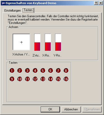 |
| The joystick-controller is
powered and controlled via USB. The capacitors C1 and C5 stabilize the
supply voltage. C2 is stabilizing the USB-voltage if the internal
3.3V-voltage regulator. Q1, C3 and C4 feed the microcontroller with a stable 20-MHz clock. R1 pulls up Pin 1 of the microcontroller to high level. The circuit is designed for a PIC18F2455. However, PIC18F2458/2550/2553 can be used as well. (No changes at the hardware or HEX-file would be necessary.) Teacher/Student-signal The microcontroller expects the PPM-teacher/student-signal at the interconnected pins 12 & 13. These are Schmitt-trigger-inputs. The high-part of the PPM-signal has to be >4V and the low part has to be <1V. The polarity of the PPM-pulses (normal or inverted) is unimportant. Never apply voltages above 5V or below 0V directly to the pins 12 &13 ! The practical output voltage levels of teacher/student-signal vary from 0.6V to 9V (depending on the brand). This signal has to be converted to the correct voltage level for the micro controller. The circuitry contains a level converter (R3, R2, C6, Q2) to convert nearly every signal level to the correct voltage level for the microcontroller. The teacher/student-signal of the RC has to be connected to the connector JP1. An LED can be connected to Pin 11 (RC0). This pin is high, if a valid teacher/student-signal is received. |
 |
| SW8 |
SW7 |
SW6 | SW5 | SW4 | SW3 | SW2 | SW1 |
| invert Channel | unused | unused | Order of Channels | ||||
| Joystick Axis |
1. Axis | 2. Axis | 3. Axis | 4. Axis | 5. Axis | 6. Axis |
| Name |
X |
Y |
Z |
X-rotation |
Y-rotation | Z-rotation |
| Function
in PC |
Aileron | Elevator | Throttle | Rudder | - | - |
| SW2 |
SW1 |
RC-Typ (Brand) |
Channel 1 |
Channel 2 |
Channel 3 |
Channel 4 |
| open |
open | Futaba / Hitec |
Aileron |
Elevator |
Throttle |
Rudder |
| open | closed |
Graupner / JR |
Throttle | Aileron | Elevator | Rudder |
| closed | open | MPX / robbe |
Aileron | Elevator | Rudder | Throttle |
| closed | closed | Sanwa |
Elevator | Aileron | Throttle | Rudder |
| SW8 |
SW7 |
SW6 | SW5 |
| Channel 4 |
Channel 3 | Channel 2 | Channel 1 |